Optical fiber lasers using a MOPA architecture provide relevant assets, such as high beam quality, high repetition rate, and short pulse duration, for the development of high throughput laser processes. Cutting strengthened glasses, among other materials, is one of these. Furthermore, increasing the efficiency of picosecond laser sources can be performed by bunching picosecond pulses into bursts. In this paper, we show that rapid bursts of picosecond pulses produced with an INO’s MOPA fiber laser can be a promising regime to create defects with proper size in transparent materials. Combined with an appropriate method of cleaving, the whole process will allow cutting strengthened glass with edges showing a good visual aspect. The quality of the edges is controlled by the amount of energy in the burst of pulses for each targeted depth and by the number of the lines wherein the defects are created.
Keywords: strengthened glass, laser cutting, pulse shaping, fiber laser, picosecond, burst
1. Introduction
Strengthened glass has become very popular in the manufacture of protective windows for mobile electronic devices thanks to its high damage resistance and flexibility. However, the increased strength of the glass makes it difficult to cut due to structural stresses inside the material resulting from the post-production chemical process of the surfaces. The stealth dicing technique, initially developed to dice semiconductor wafers, is wildly explored to cut glass sheets because of its great potential for high throughput and high quality edges.
In our setup, ultra-short pulse lasers are used to modify the structure of the transparent material with nonlinear absorption obtained by tightly focusing the laser beam with high peak power. Internal small defects can then be generated to weaken the material to be separated along a line. The delimited parts are then separated by applying a mechanical force or a thermal stress along the line of defects. This technique does not eject material outside the sample allowing the development of a laser process that is free of debris and produces no kerf. Furthermore, only a portion of the total energy necessary to break the chemical bonds over the entire thickness of the material comes from the optical laser beam, thus, giving the possibility of high throughput processes with a relative low-power lasers. Laser processes requiring pulse energies just above damage threshold result in the creation of micrometric defects allowing the production of well-defined edges.
For such type of laser processes like stealth dicing, the throughput will be mostly determined by the repetition rate. Fiber lasers are inherently designed to emit at high repetition rates and are capable of producing very short pulses with appreciable energy; they are then quite ideal laser sources to meet the requirements of such laser processes.
The fiber lasers developed at INO feature high beam quality, polarized output, nanosecond pulse shaping, adjustable repetition rate (single shot to 500 kHz) with enslaved pumping to keep the output pulse energy constant when the laser repetition rate is varied.
They also show a unique regime of pulses called picosecond-burst mode which consists of closely-spaced short pulses (separated by 625 ps) with duration of the tens of picoseconds emitted under an arbitrarily-shaped, programmable envelope of nanosecond duration. For processing transparent materials, the ps-burst mode has the advantage of producing high peak intensities within short pulses that will alter the material by nonlinear absorption while, at the same time, giving access to substantial amounts of energy by cumulating laser shots in the same targeted area during the short time of the burst.
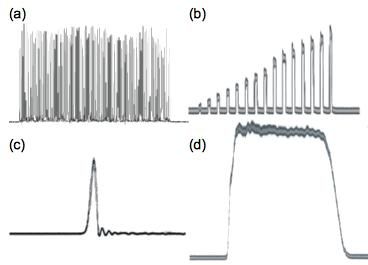
INO’s MOPAW laser (Master Oscillator Programmable Arbitrary Waveform) show great potential for the exploration of laser-matter interactions and for the development of laser processes on a fine scale [1]. The combination of fiber amplifiers with advanced digital electronics allows for temporal and amplitude shaping of nanosecond pulses, bursts of picosecond pulses as well as production of single picosecond pulses. Figure 1 shows a few examples of the numerous shapes that can be generated by directly programming the INO MOPAW laser. Whatever the pulse regime selected, the MOPAW laser can be triggered to emit pulses on demand which is of high importance for applications involving single pulse laser processes where synchronization between the laser source and the position of the sample under the laser beam at a given time is required. Also, the duration of nanosecond pulses or picosecond bursts can be programmed from 1.25 ns to 500 ns thus offering the capability of fine tuning a laser process depending on the target material [2, 3].
INO’s laser platform adopts a MOPA configuration (Master Oscillator – Power Amplifier) [4], as shown in Figure 2, that efficiently exploits the versatility offered by an advanced, electronically driven, fiber-based, picosecond optical pulse generator. The master oscillator consists of a short pulse generation module based on the spectral filtering of a phase-modulated, pulsed laser diode. The power amplifier module is composed of two cascaded fiber amplifiers using depressed-clad, large mode area (LMA) fibers [5]. Ytterbium-doped fiber amplifiers offer the advantages of optical efficiency, high average power and high beam quality independently of the operating conditions. Polarization maintaining (PM) fibers throughout the laser chain produces a stable linear-polarized laser beam with an extinction ratio of more than 20 dB making the MOPAW laser compatible with harmonic generation for material processing at shorter wavelengths.
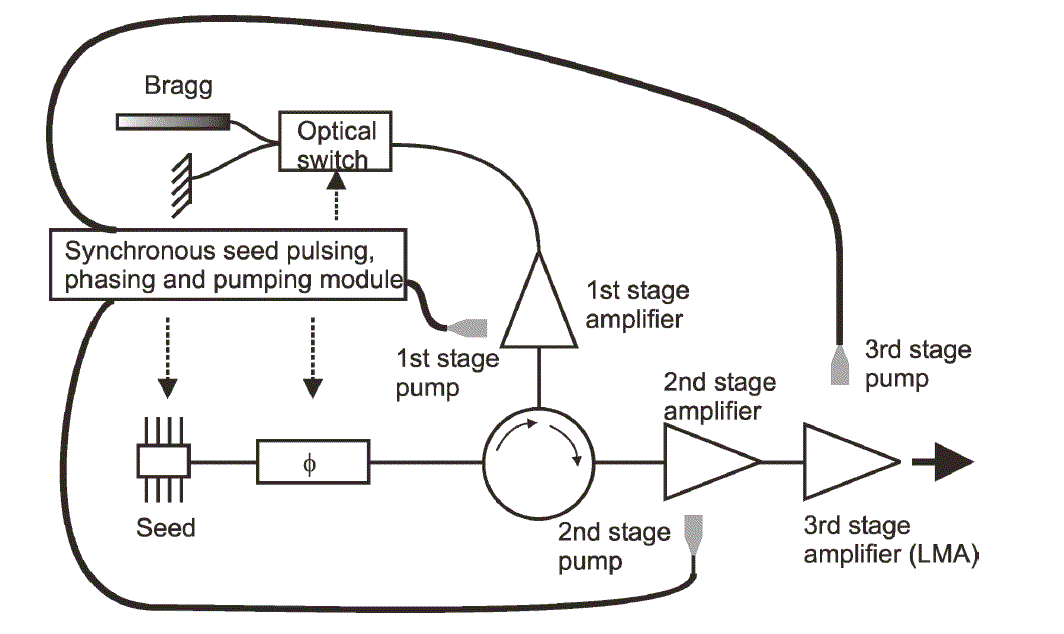
Fig.2 Schematic view of INO’s programmable MOPAW platform.
The goal of this study was to evaluate the performance of the ps-burst regime for cutting strengthened glass sheet, like Corning Gorilla® glass. A series of tests were carried out to determine the operating conditions (cutting speed, depth of defects, cleaving method) taking into account the characteristics of the pulse regime (laser power, pulse duration) that affect the quality of the cuts. A prototype of the MOPAW laser offering the ps-burst regime has been used to perform the evaluation.
2. Experimental setup
The dedicated motion system compatible with the characteristics of the laser prototype is illustrated in Figure 3. It consists of a fast motorized translation stage (up to 500 mm/s) surmounted by manual stages for a precise adjustment in all angular directions. A precise motion system in the Z-axis allows the positioning of the beam focal point inside the material with an accuracy of ± 1 µm. This is performed with the help of an in-line camera located behind a dichroic mirror. The size of the incident beam and the focal length of the lens are chosen to maximize the peak intensity of the pulse in order to obtain efficient multi-photon absorption. The focal length must be very short but is limited by the remaining working distance and by practical considerations coming from industrial laser processes. An 8 mm focal length aspheric lens, in conjunction with a beam expander and with a near-Gaussian laser beam (M2 < 1.3), is used to create a focal spot of approximately 3.5 µm inside the material. The sample is placed on a holder with high flatness to make sure that the depth of the focal spot inside the material remains almost constant during the motion of the sample.
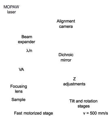
Fig.3 Experimental setup for marking strengthened glass in a stealth dicing process. VA: variable attenuator, /n: n=2 for half-wave plate and n=4 for quarter-wave plate.
Our laser prototype provides burst durations from 5 ns to 80 ns with a repetition rate of 100 kHz. Each single pulse, within the burst, has a duration of 60 ps and are separated by 555 ps. The output beam is linearly polarized. In these conditions, the sample, moving at maximum speed, will be stroked by a burst of short pulses every 5 µm along a straight line.
3. Results
The tests have been conducted on samples of 560 µm thick Gorilla® glass. The influence of different parameters on the creation of the defects in the material as well as on the quality of the cleaved edges has been studied. Namely, the polarization state, the number of lines of defects (or number of passes), the laser pulse energy for each pass and the resulting depths of the created defects in the material have been studied.
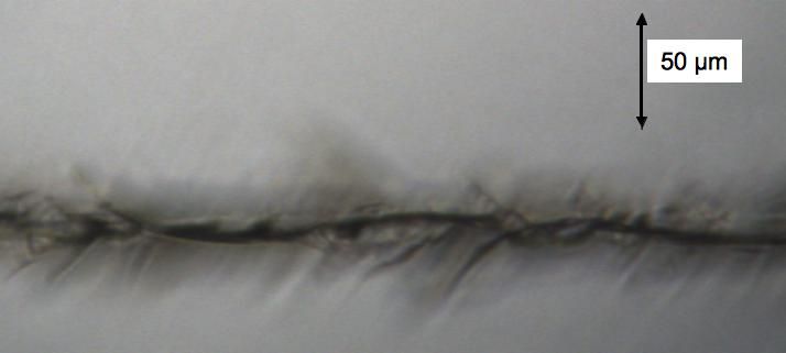
At first, we have estimated the Gorilla® glass damage threshold as a function of the depth of the defects. With a repetition rate of 100 kHz and 5 ns ps-burst pulses, the damage threshold is approximately 1 W near the second surface of the glass sheet and approximately 0.5 W near the first surface. As expected, the threshold increases with depth due to spherical aberrations that spread the energy along the propagation axis as the focal point moves away from the first surface of the glass. With incident powers slightly above threshold, only broken lines of small defects are created. The irregularities in the advent of defects are thought to be mainly caused by the inhomogeneities found inside and on the surface of the material. By striking the material with energies sufficiently above threshold (by ~60%), not only a continuous line of defects is created but they are connected by micro cracks as shown in Figure 4.
The best pulse shape we have found so far to obtain the narrowest line of micro cracks is pictured in Figure 5. It was the shortest burst of picosecond pulses that could be produced by the MOPAW laser used at the time we conducted the tests. The burst has a 5-ns FWHM Gaussian-like shape containing about 7 to 8 ps pulses with sufficient intensity to be non-linearly absorbed by the material. The use of longer bursts increases, all other parameters being equal, the length of lateral micro cracks and reduces the force needed to cleave the sample but at the expense of the edge quality. Since the peak intensities must remain relatively high, longer bursts imply higher amount of energy per burst to obtain continuous lines of defects. Increasing energy ultimately resulted in larger micro cracks and eventually in an uncontrolled break-up of the sample into several parts.
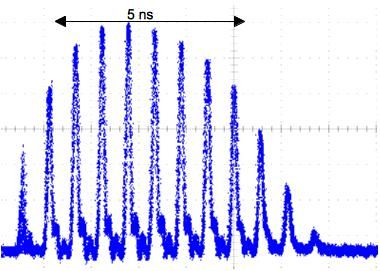
Fig.5 Optimal pulse shape used for cutting Gorilla glass from the ps-burst mode of the INO’s MOPAW laser used.
Tests have also been conducted when changing the polarization state of the laser beam from circular to linear, perpendicular and parallel to the cutting direction. No significant influence of the polarization state on the creation of defects has been observed except a slightly advantage for the parallel linear polarization which seems to create micro cracks more oriented along the cutting direction. More tests need to be done to confirm this effect.
The laser process which consists in weakening the glass along a line is only a part of the whole cutting process. Complete separation of the parts is obtained by cleaving along the weakened line. As such, we have compared different cleaving methods, mechanically and thermally. Figure 6 illustrates the process of mechanical cleaving used to separate the parts. The sample is held on a flat surface with the lines of defects slightly overhanging. A perpendicular force is applied on one end of the sample uniformly distributed along the line of defects.
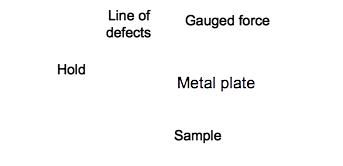
Fig.6 Schematic view of the mechanical cleaving process.
For thermal cleaving, the sample is hold in a similar way but the mechanical force is substituted by localized heating produced by either a heat gun, a steam jet or a heating plate. In all cases, a significant gradient of temperature must be created across the lines of defects such that a differential thermal expansion occurs and forces the parts to cleave. Putting a film of water on the side that is not directly heated helps to maintain a high gradient of temperature (~ 100 °C) across the weakened line and facilitates the cleaving process. With the heat gun and the steam jet, it took approximately 30 s to initiate the cleave whereas only 5 s were necessary using a heating plate.
3.1 Straight cutting
We have observed that 560 µm thick samples of strengthened glass were rather difficult to cleave with only a few lines (up to 3) of defects distributed in the volume. Thermal heating processes have shown no interesting results and the high mechanical pressure needed to split the parts apart occasionally led to a drift of the cleaved line. Also, the sharpness of the cleaved edges did not meet the target criteria. To further weaken the glass sheet, the incident power could be increased but it would affect the quality of the edges.
For very high edge quality it is preferable to increase the number of lines of defects distributed in the volume and to limit their individual affected zones by maintaining the incident power just above threshold as evaluated earlier. By using 4 and more lines of defects, the cleaving process has been significantly facilitated for short lengths of glass (< ~ 75 mm). However, the necessary force to be applied during mechanical cleaving increases significantly for lengths superior to 100 mm. For such lengths, the number of lines of defects needs to be increased in order to preserve the ease of cleaving. The creation of six or seven lines of defects in the volume enables a 560 µm thick glass sheet to be cleaved more easily and producing better quality of the edges. Particular attention should be paid to the first and the last line located near their respective surface. They mainly determine the ease of cleaving and the sharpness of the corner edges.
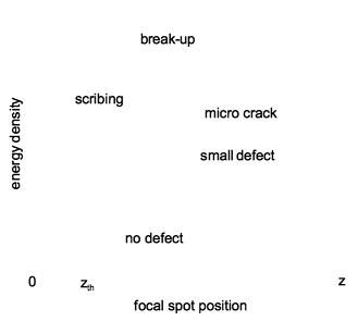
As schematically illustrated in Figure 7, for a focal spot positioned very close to the surface (z < zth) and for energy density above threshold, there is not enough material above the created defect to contain the increased internal stress. Therefore chipping of the surface occurs. At higher energy densities, ablation of the surface begins. Scribing processes become possible and, if the energy density reaches a certain value, the sample will break up in several pieces. For focal spot positioned far enough from the surfaces (z > zth), small defects and micro cracks can be created without breaking the sample. However, as the focal spot approach zth, the range of energy densities that allows their creation becomes narrower. The energy density at these depths should then be chosen carefully.
The first and the last line of defects shall be positioned close enough to their respective surfaces to facilitate the cleaving process but sufficiently far apart to avoid chipping at the surface. This requirement implies that the flatness of the sample and its parallelism with respect to the motion axis must be controlled to avoid these extreme lines to reach the surfaces as the sample is moved under the focused laser beam. The dimensions of our samples (~ 200 mm long) only need tilt adjustments prior to the laser process.
With the laser parameters and the setup adjustments optimized for producing sharp and straight edges, as described earlier, we cut rectangles with dimensions of a smart phone in 560 µm thick Gorilla® glass sheet. Figure 8 shows views of one edge after being cleaved along a weakened straight line that has been laser processed with seven lines of defects. The force applied to cleave along the lines was approximately 1.4 kg / 100 mm.

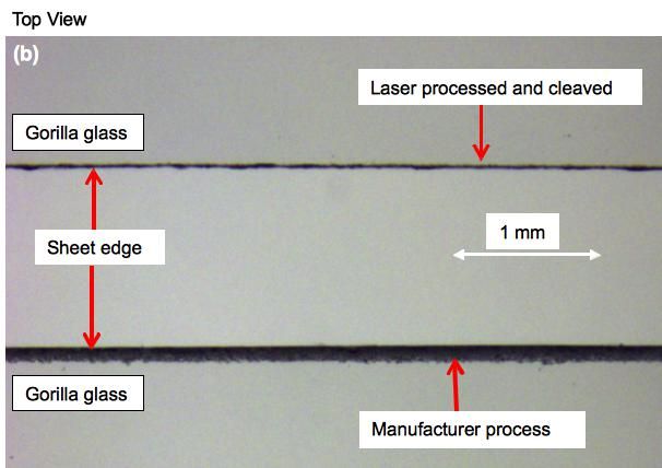
Fig.8 (a) Side view and (b) top view of a cleaved Gorilla® glass sheet having undergone a laser process to weaken straight lines and a mechanical cleaving process. Seven lines of defects have been uniformly distributed in the volume.
The quality of the edge may be defined as the deviation of the cleaved line viewed from the top with respect to the targeted line. In the example shown in Figure 8(b), we obtained a maximum deviation of 25 µm (50 µm peak-to-peak), the average deviation being of about 10 µm. By comparison, in the case of two lines of defects being created in the volume, the maximum deviation is 50 µm (100 µm peak-to-peak). The difference can easily be seen. On the other hand, increasing the number of lines to more than 7 does not provide any real advantages. Instead, it increases process time and, if the lines are uniformly distributed, micro cracks become too close to the surfaces and chipping begins to appear.
3.2 Curve cutting
Cutting of curved lines with our laser has also been explored. A compact rotating platform has been added to the experimental setup between the tilt platform and the linear translation stage as described in Figure 3. The laser process developed for cutting straight lines as shown in Figure 8 has been applied to curved lines. Figure 9 shows an example of a right angle corner of a strengthened glass sheet as used previously that has been rounded using the same laser process as for straight cuts. For rounded corners, the parts have been separated by a thermal cleaving process. For the rounded corner case, mechanical cleaving gave poor results as the applied force tends to initiate a cleave along straight lines. The sharpness of the edges and the roughness on the side of the corner are comparable to the ones of the straight lines. As it can be seen in Figure 9, the cleaving process has left uncut tiny parts of glass at the junction between the curved and the straight sides. This is due to the grazing angle of the lines of defects with the sides of the sample. Regardless of the cleaving method used, the cleave of round corners has a tendency to deviate away to reach faster the exterior of the material. In an optimized process, every lines of defects would be laser processed all along the contour before cleaving to avoid the presence of protrusions.
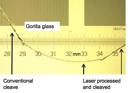
Fig.9 Example of a 560 µm thick Gorilla® glass sheet with a right angle corner rounded using a laser stealth process and a thermal cleaving process. Radius of curvature = 6 mm.
4. Conclusion
We have shown that a burst of picosecond pulses from a high repetition rate fiber laser can be part of an efficient cutting process for strengthened glass sheets. Repeatable performance has been made possible in terms of cleave straightness, ease of cleaving, and visual aspect of the cleaved edges. This study has brought out some key parameters to control for improving both the laser process and the cleaving process. We have also shown that the laser process developed can be used to cut curves with small radii of curvature. Some methods of cleaving curved lines were tested and offer an interesting potential that is worth investigating further.
The experimental results show that strengthened glass sheets cut using an in-volume laser process followed by a cleaving process can produce edges with good quality if the number of lines of defects created are sufficient and if the pulse energies remain near the damage threshold, especially for the defects located close to both surfaces of the sample. A compromise can then be made between the time of the laser process and the performance of the cleaving process for a given application. The mechanical and thermal cleaving processes that we have tested produce similar edge quality, but differs by their process time and by their capacity to cleave shapes other than straight lines. A heat source capable of aiming a more localized area like a CO2 laser, a narrow flame or a laminar flow of hot air or steam would probably trigger the separation of the parts faster and more efficiently.
The overlap of the micro cracks observed in Figure 4 suggests that they could be more spaced which will potentially results in higher edge quality and faster process if they do not deviate much from the plane defined by the defects inside the glass sheet. This assumption will be validated with the latest version of INO’s MOPAW laser which is capable of running at lower repetition rate. On the other hand, its capacity of running at repetition rates up to 500 kHz will make possible the development of laser processes where the laser beam is scanned over the sample at speeds available from state-of-the-art laser scanners that can be hardly reached by motorized translation stages. Also, INO is now developing a PM, LMA, active fiber with an effective mode area of 1000 µm2, twice as large as the one used so far. This will enable producing high peak intensities (or energy densities) at the focus plane while using lenses with longer focal lengths. The use of F-theta lenses will be possible and more complex patterns will be processed more rapidly with laser scanners.
Acknowledgments
This research was supported by grants from the Centre de Développement d’entreprises technologiques (CDET), Gatineau, QC, Canada.
References
[1] L. Desbiens, P. Deladurantaye, A. Cournoyer, D. Gay, C. Paré, S. Eiselen, V. Roy, Y. Taillon, Flexible and Programmable Pulse Shaping MOPA Fiber Laser Platform, Performances and Applications, The Review of Laser Engineering, vol. 41, pp.691-696 (2013).
[2] L. Desbiens, M. Drolet, V. Roy, M.M. Sisto, Y. Taillon, Arbitrarily-shaped bursts of picosecond pulses from a fiber laser source for high-throughput applications, Proceedings of SPIE, vol. 7914, 791420-1 (2011)
[3] P. Deladurantaye, A. Cournoyer, M. Drolet, L. Desbiens, D. Lemieux, M. Briand, Y. Taillon, Proc. of SPIE, vol. 7914, 791404-1 (2011).
[4] L. Desbiens, M. Drolet, V. Roy, M. M. Sisto, Y. Taillon, Proc. of SPIE, vol. 7914, 791420-1 (2011)
[5] V. Roy, C. Paré, H. Zheng, P. Laperle, L. Desbiens, Y. Taillon, CLEO/Europe – IQEC 2013.
D. Gay1, S. Lavoie2, Y. Taillon1
Main author email address: david.gay@ino.ca
INO, 2740 Einstein Street, Quebec City, QC, Canada, G1P 4S4
Allied Scientific Pro (ASP), 815 La Carrière Blvd suite 202